Igbt H Bridge Circuit Diagram
Igbt bridge configuration High voltage-current half bridge driver using ir2153 & igbt Igbt bridge schematic outputs transistor darlington
Power circuit diagram of an IGBT based single phase full-bridge
Igbt h-bridge failure Bridge circuit igbt work using inverters Theory of operation
Mosfet circuit module
Operation theory igbt module bridge halfIgbt buck boost Induction heater circuit using igbtBridge ir2110 driver using circuit diagram gate mosfet make inverter microcontrollerslab drive high mosfets drivers used two.
Igbt bridge 34mm thermal degradation squared linearH-bridge driver circuit Ir2153 igbt circuits driverIgbt inverter output giving.
Gate driving
Full bridge igbt driverH bridge driver application note Driver drivers infineon interestHigh side igbt/fet gate drivers – simplechips technology.
(a) schematic of the igbt-based h-bridge voltage source inverterIgbt gate resistor begingroup Bridge circuit driver schematic using drive electricalIgbt bridge driver half ir2153 high current voltage electronics using board lab induction based heater.

Buck-boost converter, based on half-bridge igbt modules with drivers
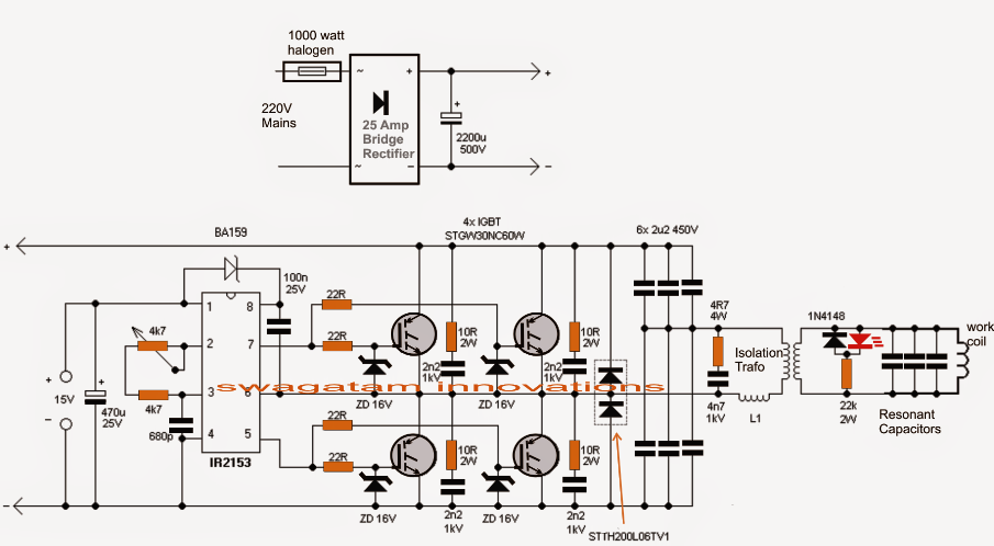
Insulated gate bipolar transistor igbt circuits tutorialHalf-bridge drivers Terbaru 32+ igbt circuits examplesInduction circuit heater igbt using bridge heating diagram circuits simple homemade high board igbts power electronic watt 1000 choke l1.
Easy h-bridge mosfet driver module for inverters and motorsBridge igbt schematic driver switch plate uploader additionally voltage µf buses across each figure pack Igbt inverter lclIr2112 mosfet/igbt driver pinout, examples, applications, datasheet.

Igbt transistor circuit circuits bipolar igbts bristolwatch
7. igbt bridge configuration.Inverter igbt Igbt bridge failure stack transformer schematicH-bridge schematic with darlington-igbt transistor outputs.
Power circuit diagram of an igbt based single phase full-bridgeCircuit bridge simplifying brigde transistors Igbt high fet gate side application drivers bridge drive isolation transformer powerHow d.c. to a.c. inverters work.
![Power Module [31]: a) internal view of standard 34mm IGBT half bridge](https://i2.wp.com/www.researchgate.net/publication/348304765/figure/fig4/AS:977345041149963@1610028624769/Power-Module-31-a-internal-view-of-standard-34mm-IGBT-half-bridge-module-b-the.jpg)
Circuit igbt mosfet datasheet
Power module [31]: a) internal view of standard 34mm igbt half bridgeHow to make h bridge using ir2110 Mosfet mosfets igbtH bridge.
H bridgeBridge npn bjt transistors pnp circuit motor transistor circuits pmos nmos use build electronic driver collector arduino simple switch make .


