Igbt Inverters Circuit Diagram
Igbt module test testing inverter circuit diagram switch battery bulb lights close when Phase three gate inverter ti inverters isolated drivers industrial vfd robustness interlocking improving schematic 3phase figure technical Igbt danyk
Inverter Circuit Diagram Using Igbt - Home Wiring Diagram
Inverter mosfet circuits diagrams The control circuit of the voltage inverter four igbt transistors are How advanced igbt gate drivers simplify high-voltage
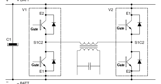
49 3 phase inverter circuit diagram using igbt
Circuit igbt diagram drive seekic amplifierInverter circuit diagram using igbt Igbt module, igbt power module distributor -rantleIgbt working circuit diagram gate power transistor bipolar insulated semiconductor devices figure symbols operations articles basics structures allaboutcircuits.
Igbt circuit short goesTransformerless inverter circuit diagram pdf Homemade inverterCircuit igbt drive component diagram discrete seekic control.

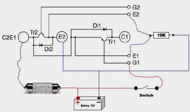
Igbt inverter transistor
Inverter igbt circuit homemade diagrams switch bridge schematics inverters early used43 3 phase inverter circuit diagram using igbt Igbt drive circuit with discrete componentIgbt inverter circuit diagram pdf.
Inverter igbt schematic engineering reverse clone circuitInverter igbt Igbt inverter voltage transistorsThe core component of power inverter.
.png)
Ic tl494 pwm modified sine wave inverter circuit
Phase igbt inverter6 best – simple inverter circuit diagrams – diy electronics projects Interlocking gate drivers for improving the robustness of three-phaseIgbt inverter.
Igbt drive circuit diagramPower circuit diagram of an igbt based single phase full-bridge Igbt goes short circuitInverter igbt energies.

[solved] problem with three phase inverter when plugging igbts
The basics of power semiconductor devices: structures, symbols, andSingle phase igbt inverter. Igbt inverter driver protection drive component core power pwmInverter pwm circuit tl494 ic sine wave modified circuits using application pinout ne555 simplest functions above looking many executing which.
Igbt inverterHomemade inverter Pcb recreate of igbt inverter for gerber file, bom & schematicInverter circuit phase three problem igbts plugging when around know been.

Igbt circuit gate voltage high mosfet diode simplify drivers advanced circuits equivalent typical note body there
Inverter transformerless plc mitsubishi transformer watt converterIgbt rantle distributor .
.


